General information
Design and function
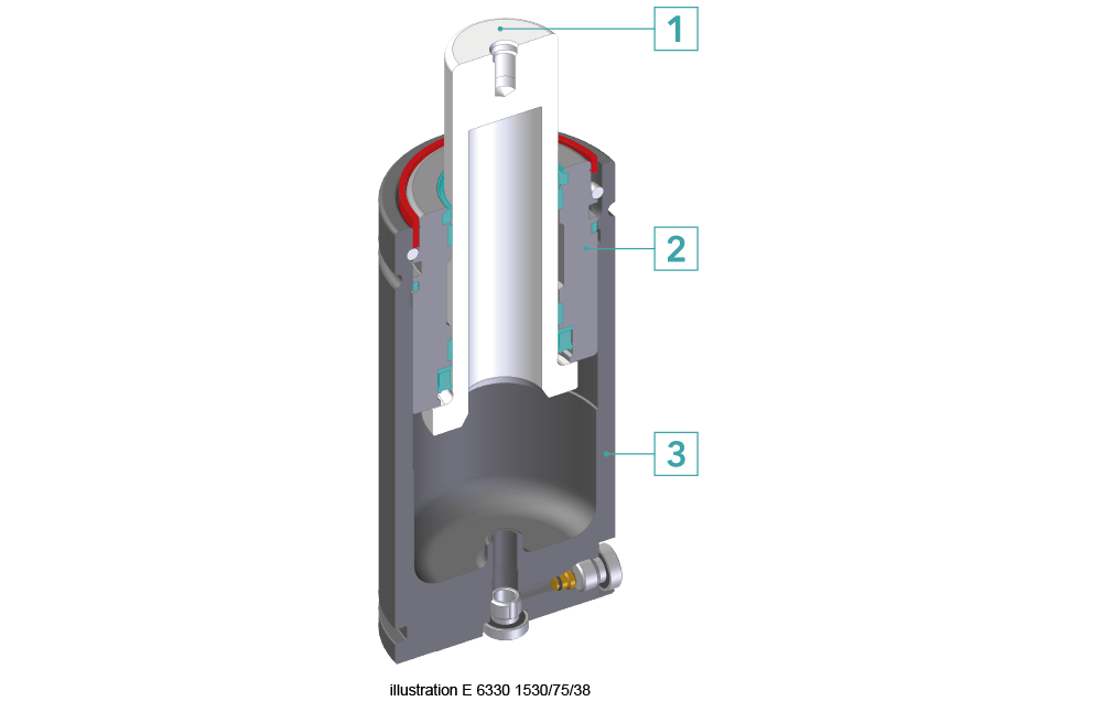
Gas springs are cylinders filled with nitrogen (N2) and use highly pressurised gas for providing the spring force required. Nitrogen is a colourless, odourless and tasteless gas. It is non-flammable and therefore completely harmless. A gas spring is essentially made up of the following three components (the design varies depending on the type):
1 – Piston rod (Superfinish surface)
2 – Bush
3 – Body
All gas springs from Meusburger comply with the Pressure Equipment Directive PED2014/68/EU which came into force in 2016. This directive describes and regulates the requirements for pressure equipment within the European Economic Area.

Gas spring vs. system compression spring
A gas spring requires significantly less space than a system compression spring with the same force.

The full initial force is available at the beginning of the stroke so no preload is necessary.

Information:
The initial force for gas springs is usually given in daN (decanewtons) . This unit corresponds approximately to the weight acting on a mass of 1 kg.
Example: an initial force of 4 daN corresponds to about 4 kg.
In addition, the installation height needed for a gas spring is less than for a system compression spring with the same stroke and force.

Gas springs also have limits
Despite the many advantages already mentioned, there are also limits in the use of gas springs. For example, gas springs can only be used up to a limited number of strokes. Especially for high-performance die-cutting at very high stroke rates system compression springs are still the best option. Due to their more complex construction, gas springs are also usually more expensive than system compression springs.
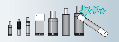
Different types
Everything at a glance

Safety first!
The purpose of the safety features is to protect the user and ensure that the use of a gas spring does not result in dangerous situations for the machine operator.
Over Stroke Active Safety
This safety feature enables automated, controlled and full pressure release in the case of overstroke. This minimises the risk of separation and ejection of pressurised parts. The pressure release is made through the provided discontinuity grooves on the body or the rupture protection elements in the bottom plate.
Video

Over Stroke Marker
- Shows that the OSAS overstroke protection has been activated.
- Enables you to directly eliminate the cause of overstroke in the die.
- Does not restrict the free positioning of the gas spring.

Uncontrolled Speed Active Safety
Enables controlled and full pressure exhaust in the case of an uncontrolled piston return. Minimises the risk of separation and ejection of pressurised parts. The pressure release is made through the provided discontinuity grooves on the body or piston rod.
Video

Over Pressure Active Safety
Active safety device enabling controlled and full pressure exhaust if the maximum permissible stroke is exceeded. This minimises the risk of separation and ejection of pressurised parts. Pressure release is via rupture plug or via integrated rupture protection elements in the bottom plate.
Video

Selection guide
Thanks to our wizard you can quickly and easily find the right gas spring for your project.
How exactly does this work?
With just a few clicks and specifications, the appropriate gas springs are displayed immediately. After you have placed the desired gas spring in the shopping basket, you can download the 3D data as usual. The configurable CAD data offers a great advantage here. In addition to the CAD data for the completely extended or compressed spring, you can also enter other values and then immediately download the corresponding CAD data. This saves you valuable time and therefore also money.
Gas spring wizard
Tips for correct installation
- If possible, always attach the gas spring to the die.
- Use a suitable threadlocker such as Meusburger VBA 2M43.
- Always observe the correct tightening torques as indicated.
- Check the condition of the gas springs and the fasteners after each modification on the die.

| Screw DIN EN ISO 12474:2011-01 class ≥ 8.8 | M5 | M6 | M8 | M10 | M12 | M16 |
|---|---|---|---|---|---|---|
| Tightening torque in Nm | 6 Nm | 10 Nm | 24 Nm | 50 Nm | 84 Nm | 205 Nm |
Dos and Don'ts

- Do not use a vice to check the cylinder’s force.

- Always position the gas spring perpendicular to the surface. Avoid any radial load during piston rod compression. Always apply pressure to the entire end surface of the piston rod. As much as possible, equalize the load in the die.

- Use the threaded hole on the piston rod for transport of the gas spring only. This hole may not be used to fix the gas spring.

- Do not carry out any mechanical work on the cylinder or the piston rod.

- Any uncontrolled return stroke of the piston rod must be avoided as it may cause damages or mechanical failures on the cylinder or fixings.

- Do not use any gas other than nitrogen N2 to fill the gas springs.

- Protect the gas springs from aggressive solids and fluids (such as sodium carbonates and chlorides). If they are used to clean the die, remove any residue from the gas springs.

- It is recommended to have a stroke reserve of 10% of the nominal stroke length or 5 mm for strokes longer than 50 mm.

- Do not use the gas spring at temperatures higher than 80°C/176°F.

- Do not use the gas spring at a speed over 0.8 ÷ 1.8 m/sec.

- Do not charge cylinder over the maximum allowed charging pressure laser etched on the body.

- During the discharging procedure, place the cylinder upside down and direct the gas flow away from the operator.

- If damage is suspected, the gas spring must be depressurised immediately while still in the installed position. This can be done by opening the valve or drilling a hole in the cylinder body until the gas has been discharged.
Installation options
Installation in a blind hole
Ensure that the contact surface is not interrupted or obstructed. After any modification to the die, check the gas spring‘s condition and its proper fit.

Top mount
Top mount with flange

Base mount
Base mount with flange

Bottom mount
Use screws of a suitable length to use the full depth of the threaded hole on the cylinder.

Maintenance
If the load limits stipulated by VDI 3003 (see chart) are exceeded, maintenance is required. The service can be carried out by Special Springs or independently on site by ordering the suitable maintenance kit that is delivered with a user manual. The maintenance kit code (Man. Code) is marked on the gas springs.


Pressure release device
For complete release of the gas spring’s pressure
Filling adapter
For refilling the gas spring

Tips for the correct storage of gas springs
- Storage in upright/horizontal position is no problem.
- Avoid storage with the piston rod pointing downwards.
- Storage in a dark place is not necessary, however we recommend avoiding direct sunlight.
- The gas spring can be stored for 1 to 2 years.
- The ambient temperature should be between 0° and 35°C.
- The best storage conditions are in closed rooms, with some ventilation, free of humidity and especially free of dust. Handle the gas springs carefully to avoid dents or scratches, especially on the piston rods.
- Avoid contact with corrosive chemicals and the vapours they emit.
- It is not necessary to lubricate the piston rod. Our gas springs are sufficiently lubricated before shipment.
- Please avoid cleaning the piston rod in order not to remove the lubricant and thus cause corrosion.



 © 2024 by Meusburger Georg GmbH & Co KG | All rights reserved



 Česká republika [CS]
 Danmark [DA]
 Deutschland [DE]
 España [ES]
 France [FR]
 India [EN]
 Italia [IT]
 Magyarország [HU]
 México [ES]
 Nederland [NL]
 Österreich [DE]
 Polska [PL]
 Portugal [PT]
 România [RO]
 Schweiz [DE]
 Slovenija [SL]
 Srbija [SR]
 Suomi [FI]
 Sverige [SV]
 Türkiye [TR]
 United Kingdom [EN]
 USA [EN]
 Ελλάδα [EL]
 България [BG]
 Росси́я [RU]
 华 [ZH]